Phone: +86-133 5263 6504
Phone: +86-133 5263 6504
Usage Methods of LED Potting Compounds: From Mixing to Curing – A Complete Step-by-Step Guide
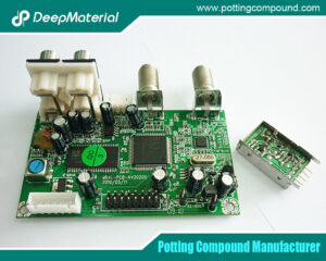
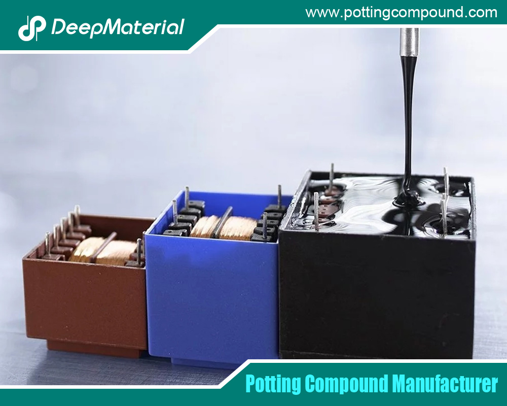
LED potting compounds—also known as encapsulants—are two-component (or occasionally single-component) thermosetting polymers designed to protect sensitive electronic components, especially LED drivers, modules, and power supplies, from moisture, vibration, thermal shock, dust, and electrical interference. These materials, typically epoxy, polyurethane, or silicone-based, form a rigid or flexible barrier that enhances reliability and extends service life in harsh environments such as outdoor lighting, automotive headlamps, and industrial controls.
Proper usage is critical: incorrect mixing, inadequate defoaming, or improper curing can lead to voids, poor adhesion, reduced thermal conductivity, or even catastrophic failure. According to industry failure analysis, over 60% of field returns in LED power modules stem from encapsulation defects. Yet, when executed correctly, potting compounds achieve >99.9% reliability over 50,000 hours.
- Understanding LED Potting Compound Types
Before diving into usage, recognize the three dominant chemistries:
| Type | Key Properties | Typical Applications | Cure Mechanism |
| Epoxy | High strength, excellent adhesion, thermal conductivity (0.8–2.0 W/m·K), rigid | LED drivers, power supplies, COB modules | 2K, heat or RT cure |
| Polyurethane (PU) | Flexible, shock-absorbing, good low-temp performance | Streetlights, flexible strips | 2K, RT or mild heat |
| Silicone | Ultra-flexible, -60°C to 200°C, optically clear or thermally conductive | High-power LEDs, optics | 2K or 1K, addition cure |
Example: A 100W LED driver uses thermal conductive epoxy (1.5 W/m·K) to sink heat from MOSFETs; a flexible LED strip uses PU to withstand bending.
Each type follows a similar workflow, but ratios, pot life, viscosity, and cure schedules vary.
- Pre-Usage Preparation
2.1 Material Storage & Conditioning
- Store A/B components at 15–25°C in sealed containers. Avoid >30°C or <5°C.
- Condition before use: Let drums reach room temperature (4–6 hours) to prevent moisture condensation.
- Check shelf life (typically 6–12 months). Use FIFO (First In, First Out).
- Inspect for settling: Epoxy fillers (alumina, silica) may sediment—pre-stir Part A gently.
2.2 Workspace Setup
- Cleanroom Class 100,000 or better for optics; ventilated area for general potting.
- Temperature: 22–26°C; Humidity: <60% RH (prevents amine blush in PU).
- Tools: Digital scale (±0.1g), planetary mixer, vacuum chamber, dispensing gun, curing oven.
2.3 Safety
- Wear nitrile gloves, safety glasses, and lab coat.
- Use local exhaust for VOCs (especially PU isocyanates).
- Have spill kit and SDS on hand.
- Step-by-Step Usage Method: LED Driver Power Potting (Epoxy Example)
We now detail the standard operating procedure (SOP) for potting a 150W LED driver using two-component thermal conductive epoxy (Mix ratio 100:25 by weight, pot life 30 min, Tg 110°C).
Step 1: Full Stirring of Components A and B
Why?
- Part A (resin + fillers) settles over time.
- Part B (hardener) may crystallize in cold storage.
How?
- Open Part A drum. Use a low-speed paddle mixer (300–500 RPM).
- Stir clockwise then counterclockwise for 3–5 minutes until uniform (no streaks).
- Scrape sides and bottom.
- Repeat for Part B (avoid air entrapment).
Pro Tip: For 200 kg drums, use automatic planetary stirrers. For 1 kg kits, hand-stir with a spatula.
Common Mistake:
Skipping this step → filler segregation → reduced thermal conductivity and voids.
Step 2: Weigh and Mix in Proportion
Why?
Incorrect ratio → incomplete cure, brittleness, or sticky surface.
How?
- Tare a clean mixing cup on a digital scale.
- Dispense Part A: 100 parts (e.g., 500 g).
- Dispense Part B: 25 parts (e.g., 125 g) → Total: 625 g.
- Tolerance: ±1% (e.g., 123.8–126.3 g for Part B).
Mixing Method:
| Scale | Method |
| <5 kg | Hand mix with spatula (2 min) → planetary mixer (500 RPM, 3 min) |
| 5–50 kg | Dual-axis centrifugal mixer (e.g., Thinky ARE-310, 2000 RPM, 2 min) |
| >50 kg | In-line static mixer with metering pumps |
Visual Check: Color should be uniform (e.g., gray → no white streaks).
Pot Life Begins Now
- 30-minute window at 25°C.
- Pot life halves every 10°C rise → work fast in summer.
Step 3: Defoaming – Natural or VacuumWhy?
Air bubbles act as:
- Thermal insulators
- Stress concentrators
- Moisture traps
Natural Defoaming (Small Batches)
- Let mixed compound sit in cup for 5–10 minutes.
- Bubbles rise and pop.
- Suitable for low-viscosity (<3000 cP) materials.
Vacuum Defoaming (Recommended for Drivers)
- Pour mixture into a vacuum chamber.
- Pull vacuum to –0.09 MPa (50–100 mtorr).
- Hold for 5–8 minutes.
- Watch for foam rise → release vacuum slowly to avoid overflow.
Equipment: Desiccator or industrial vacuum pot (e.g., Abbess Instruments).
Defoaming Time vs. Viscosity
| Viscosity (cP) | Vacuum Time |
| <5,000 | 3–5 min |
| 5,000–15,000 | 6–8 min |
| >15,000 | 10–12 min + pre-heat to 40°C |
Result:
99.9% bubble-free compound, critical for thermal pads near IGBTs.
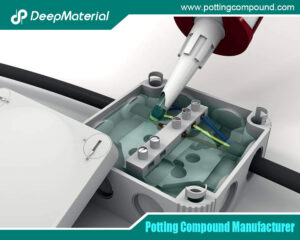
Step 4: Pouring Within Operating Time
Operating Time = Pot Life – Defoaming Time
- Example: 30 min pot life – 8 min defoam = 22 minutes to pour.
Pouring Techniques
| Method | Best For | Description |
| Manual Pour | Prototypes | Tilt PCB at 15°, pour slowly from corner |
| Dam & Fill | High-density boards | Build silicone dam → fill with potting |
| Pressure Pot Dispensing | Volume production | 0.1–0.5 MPa air pressure, needle valve |
| Jet Dispensing | COB LEDs | Non-contact, 0.1–1 mm dots |
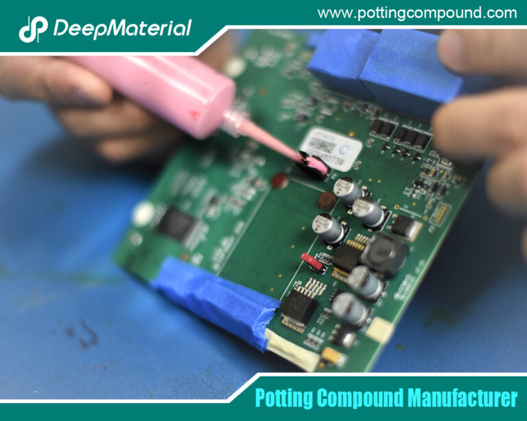
LED Driver Specifics:
- Mask connectors with Kapton tape.
- Pre-heat PCB to 40°C → reduces viscosity, improves wetting.
- Pour in spiral pattern from center outward.
- Ensure full coverage of transformers, capacitors, and PCB traces.
- Fill to 1–2 mm above tallest component.
Avoid: Pouring too fast → air entrapment.
Step 5: Curing – Room Temperature or Heating
Cure Schedule Options
| Method | Schedule | Pros | Cons |
| Room Temp (25°C) | 24–48 hours | No oven, low stress | Slow, dust risk |
| Heat Cure | 80°C × 2 hrs or 100°C × 1 hr | Fast, full crosslink | Thermal stress on components |
Recommended for LED Drivers:
- 80°C × 2 hours in forced-air oven.
- Ramp rate: 2–3°C/min to avoid bubbles from rapid outgassing.
- Support fixture to prevent component shift.
Cure Verification
| Test | Method | Pass Criteria |
| Hardness | Shore D durometer | ≥75 |
| Tg | DSC | >100°C |
| Adhesion | Pull test | >5 MPa |
| Visual | Cross-section | No voids >0.5 mm |
FTIR Check: Epoxy peak at 910 cm⁻¹ should disappear.
- Variations by Application Type
4.1 COB (Chip-on-Board) LED Encapsulation
- Material: Optically clear silicone (RI 1.41)
- Mix Ratio: 10:1 or 1:1
- Defoaming: Mandatory (optics hate bubbles)
- Pouring: Glob-top or dam-fill
- Curing: 150°C × 1 hr (addition cure, no byproducts)
4.2 Flexible LED Strips
- Material: Soft PU (Shore A 30–50)
- Mixing: 1:1 by volume (easier for field use)
- Curing: RT 24 hrs (flexible cure)
4.3 Outdoor Floodlight Drivers
- Material: Flame-retardant epoxy (UL 94V-0)
- Additive: UV stabilizer (prevents yellowing)
- Curing: 100°C × 90 min
- Troubleshooting Common Issues
| Problem | Cause | Solution |
| Bubbles after cure | Poor defoaming, high humidity | Extend vacuum time, use desiccant |
| Sticky surface | Under-cure, wrong ratio | Verify mix ratio, increase cure time/temp |
| Cracks | High shrinkage, fast heat | Use low-shrink epoxy, slow ramp |
| Poor thermal transfer | Filler settling | Pre-stir Part A, use anti-settling grade |
| Delamination | Contaminated PCB | Plasma clean or flux remover |
- Advanced Techniques
6.1 Automated Potting Lines
- Metering: Gear pumps with ±0.5% accuracy
- Mixing: Dynamic mixer head
- Dispensing: 6-axis robot (e.g., Nordson Asymtek)
- Curing: Inline tunnel oven with IR + convection
6.2 Vacuum Pressure Impregnation (VPI)
- For deep potting (>50 mm)
- Cycle: Vacuum → Pour → Pressurize (0.5 MPa) → Cure
6.3 In-Mold Potting
- Inject compound into sealed housing → cure in place
- Used in IP67 LED fixtures
- Quality Control & Standards
- IPC-CC-830C: Qualification of conformal coatings (includes potting)
- UL 94V-0: Flame retardancy
- IEC 60529: IP67/IP68 ingress protection
- RoHS/REACH: No heavy metals, low VOC
QC Tests:
- Leak Test: Helium mass spectrometry
- Thermal Cycling: –40°C to 125°C, 1000 cycles
- Hi-Pot: 1500 VAC, 1 min
(Word count: 1848)
- Case Study: 200W LED Driver Potting
Client: Tier-1 outdoor lighting manufacturer
Issue: 8% field failure due to moisture ingress
Old Process: Manual pour, RT cure, no defoaming
New Process:
- Auto-stir A/B (5 min)
- 100:20 ratio via metering pump
- Vacuum defoam 7 min
- Robotic dam-fill
- 80°C × 2 hr cure
Results:
- Yield: 98.2% → 99.7%
- MTBF: 80,000 hrs → 180,000 hrs
- Cost saved: $120K/year in warranty
Conclusion
Mastering the usage of LED potting compounds transforms a liability into a competitive advantage. The core workflow—stir → weigh → mix → defoam → pour → cure—is universal, but success lies in precision at every step. For LED driver power potting, full stirring of A and B, accurate ratio mixing, thorough vacuum defoaming, and controlled heat curing are non-negotiable.
As LED technology pushes toward higher power density (e.g., 500W drivers, COB arrays >200W), potting compounds evolve with higher thermal conductivity (3–5 W/m·K), faster cure, and automated compatibility. By standardizing these methods, manufacturers achieve zero field failures, faster time-to-market, and certifiable reliability.
Implement this SOP, train your team, and audit monthly. The result? LED products that don’t just light up—they last.
For more about usage methods of LED potting compounds: from mixing to curing – a complete step-by-step guide, you can pay a visit to DeepMaterial at https://www.pottingcompound.com/ for more info.